Tuesday, 5 February 2019

Compiling for Wallet and MasterNode

I have had few struggle to compile some wallets and here some handy information

Make sure you install the package which must be installed before compiling

sudo apt-get install libdb-dev libdb++-dev libboost-all-dev libqrencode-dev qt4-qmake libqtgui4 libqt4-dev automake

If you need to compile the GUI, make sure you have the QT packages otherwise the configure file will skip it

sudo apt-get install libqt5gui5 libqt5core5a libqt5dbus5 qttools5-dev qttools5-dev-tools 

Another important dependency is the old version of DB, therefore you will have to install the 4.8 version. This is not a mandatory step because you can compile with the incompatible db flag, but it will not guarantee it will work.

sudo add-apt-repository ppa:bitcoin/bitcoin
sudo apt-get update
sudo apt-get install libdb4.8-dev libdb4.8++-dev

The incompatible flag is
./configure --with-incompatible-bdb


For Wallet:


  1. Clone the repo of the wallet
  2. Enter the root for the repo
  3. ./autogen.sh
  4. ./configure
  5. make


Once is finished you will have few executable files and under QT folder you will have the GUI version.

For Masternode:
  1. Clone the repo of the wallet
  2. Enter the root for the repo
  3. ./autogen.sh
  4. ./configure --without-gui 
  5. make


Issues:

checking whether htole64 is declared... yes
checking whether be32toh is declared... yes
checking whether be64toh is declared... yes
checking whether htobe32 is declared... yes
checking whether htobe64 is declared... yes
checking for MSG_NOSIGNAL... yes
checking for library containing clock_gettime... none required
checking for visibility attribute... yes
checking whether C++ compiler accepts -fvisibility=hidden... yes
checking for Berkeley DB C++ headers... default
configure: error: Found Berkeley DB other than 4.8, required for portable wallets (--with-incompatible-bdb to ignore or --disable-wallet to disable wallet functionality)

Solution:

/configure  --with-incompatible-bdb


Issue:

configure: error: Detected LibreSSL: This is NOT supported, and may break consensus compatibility!

Solution:

Install only one version of the SSL package, make sure you dont have multiple version
apt-get install libssl1.0-dev

Monday, 13 November 2017

Touchscreen Raspberry Pi


Description
Raspberry Pi is a great machine that people want to make amazing stuff with it, and one great think is to use the a visual interface that you can get from the hdmi port.
In my case I wanted to have a screen and touch sensor to interact with a custom GUI.

Item

  • Innolux 7 with touch screen (link)
  • Raspberry Pi ( in my case version 2 )
  • Battery pack
  • USB to DC Jack


Installation

1) Driver
The good news is that Raspberry Pi has finally introduced a simple  system to enable touch screen with most common board on the market ( here a list ) but in my case I had to enable Egalax sensor.

To make sure your device is supported, just connect the usb and run ( make sure its the only device usb connected)
lsusb
and you should see the model and manufacture of the sensor.

In my case everything is supported, if your sensor is not supported, try to poke them on github otherwise you are forced to recompile the kernel with the driver built-in.

The module kernel ( if supported ) has to be enabled by running the command and the sensor connected in the usb slot:
 rpi-update
when the process will be completed, you should be able to access the device.

2) Testing
Make sure you have installed all the tools to test your sensor by running this command:
 sudo apt-get install evtest tslib libts-bin

When you have confirmed that, you have to find the right path to your device by looking into the folder /dev/input/.
The common path are  /dev/input/event0 or /dev/input/touchscreen, but make sure you dont have a keyboard or mouse connected otherwise it might be event1 , event2, etc.. 

After you have discovred the correct path, in my case /dev/input/event0, try to run the command:
sudo evtest /dev/input/event0
and you should see some values after you pressed the  touch screen.
If nothing happened, that means you sensor is not connected properly or the driver module is not loaded.

3) Calibrate
Now that you made sure that the device is plugged, module loaded and something is coming out from the device, you can run the first calibration command:
sudo TSLIB_FBDEVICE=/dev/fb1 TSLIB_TSDEVICE=/dev/input/event0 ts_calibrate
after this command has been launch, you should see a calibration screen where you are asked to press 5 different spots.

Once the calibration is completed, you should have a file at the location /etc/pointcal.

Double check that you can draw correctly with this command:
sudo TSLIB_FBDEVICE=/dev/fb1 TSLIB_TSDEVICE=/dev/input/event0 ts_test
then you are ready to go!

4) Issues
You might have some problems by using the device Egalax ( as I had ), which is the missing module in the latest build of  libts-bin ( probably if this guide is a few weeks older, this problem would have been solved ).

I couldn't run the calibration test because the software would close by saying "sensor not supported", this is because the build dint have the Egalax driver embedded in the build.
What you have to do, is to make sure libts-bin is removed from your system and purged all references, usually by using:
apt-get remove --purge libts-bin

Make sure you got all the software to compile the source code of libts:
sudo apt-get install git automake libtool

Checkout the repository ( apparently the patch for the driver has been included on the main repo ):
git clone git://github.com/kergoth/tslib.git
cd libts
and compile
./autogen.sh
./configure
make
sudo make install

then follow the guide here that is just moving the library in the right folder: https://myraspberryandme.wordpress.com/2015/02/12/making-an-egalaxpollin-touchscreen-work-with-tslib/ (pointless to re-write what this guy did best )

Once you finished, you should be able to run ts_calibrate without any errors.

Also, you might want to change some parameters into /etc/ts.conf.

Pygame without X server

You small game, application, script or else dont always need to have a X server running just to access to the graphical unit.
The trick is to use pyscope, offered by Adafruit ( link ), that is a simple class which makes sure your software will inject the output of pygame into the frame buffer.

In my case I had to add few environment variables to make sure that the touch screen would work with pygame:

#Reference to the calibration file
os.putenv('TSLIB_CALIBFILE', '/etc/pointercal')
#Point to the right library folder
os.putenv('TSLIB_PLUGINDIR', '/usr/lib/arm-linux-gnueabihf/ts')
#Setup the touch screen
os.putenv('SDL_MOUSEDRV', 'TSLIB')
os.putenv('SDL_MOUSEDEV', '/dev/input/event0')
otherwise the pointer would be jumpy or not following correctly as the ts_test was showing.

Saturday, 5 November 2016

Send AGPS to UBLOX

I wanted to send AGPS data to my UBLOX CAM-M8, so get a faster fix as the chip doesnt have a eeprom to save the data and not even a battery backup.
I understood that every chip needs to download a map of where all the satellites are in the space and then based on that information, the chip can triangulate the position.

The great information is that UBLOX provides a free access to the AGPS servies which you will need to provide a close location ( latitude and longitude) and then a file is generated.

To send this file, you will need to parse the data and send the message via Serial and because I couldnt find anywhere a sample code, I tried to code something which actually worked.

The real sending would be too check the ack message, but this worked fine for me.

Saturday, 7 November 2015

PN53x with Raspberry Pi and Python


Install libnfc on your raspberry pi by following Adafruit guide , make sure you are using the Serial pins and shorted the right pins on the board, check the version of the PN53x to short the right ones.

Install the library NFCPY which allows you to read and write through libnfc a nfc tag.


To decode a message:


To write a message

Saturday, 18 July 2015

[Arduino] Timestamp function

Arduino don't have the function which convert hhmmss and ddmmyy to unix timestamp and because I was looking to combine my data to one universal time, I did't find a method to achieve that.

I came across to the library TIME which is a good library but because I had to optimise my code and have the sketch as small as possible ( developing for Arduino pro mini ), I extracted the necessary function  and variables to generate timestamp.
The file is available on my github here and this is how you can use the function:

From the date:01.06.2015 and time 20:10:00 you will have call the function like this:


and it will return a long number which is unix timestamp.

Saturday, 13 December 2014

Remove Passphrase from SSH Key


Most of the time you create a ssh key for your GIT or SSH login and you wished the system wouldn't ask the password each time, and here there is a solution to it.

openssl rsa -in private_key_with_pass_phrase -out private_key_without_pass_phrase
WARNING: a pass phrase is an added layer of security in case you loose control of your private key. Think carefully about removing the password.

Just replace the old key with the new one and you solved your problem.

Sunday, 26 October 2014

J/Box2D first steps

I came across to use JBox2D and I didnt know anything about how a physical engine works, so I am writing some helpful tips here.

Scale and dimensions

Firstable you have to keep on your mind that Box2D works with meters, so forget pixel or dpi, you will need to use some functions to convert these measurements to something that the engine can understand.
In general people use a scale, because the engine works in a world of 100x100 meters, so its better to have it as small as possible. The common scale is 30.

Here a simple way to convert pixel to Box2D dimensions:


Create a simple ball

Let's start with the second step, you have to define all properties of the object, if its a ball, it has to have  round shape and be elastic.

So you have to define the body definition, if the object will be static or dynamic  and set the position in the world:


The position might be tricky to understand, but here is a simple solution:
When you want to draw something in a canvas, you draw something from position (X,Y), so if you want to draw something at the top left corner, you will choose (0,0).
So in this thinking you would put new Vec2(0,0) in this case, but this will be WRONG because in Box2D everything works in another way, you have to tell the position of the centre of the object.

If you object is  10x10 and you want to position to the top left corner, you position will be (5,5).

To continue the body creation, you have to tell the world that this object exists in the engine, so you have to call the method "createBody"


Then tell at the body, what kind of shape your object will be:


In this case we create a CircleShape, because its a ball. In other case you have to use PolygonShape to create a special shape or a simple square.

Another tricky to understand how to create a PolygonShape for a square is the follow:

You have to use "setAsBox", and the dimension that you put inside must to be half of the width and half of the height, because the BodyDefinition has the position of the centre of the object.

Last thing to complete the creation of the ball in the world is the Fixture Definition:


You can change the density, that is the weight of the object, the friction between objects and the restitution that is the elasticity. Play with some values and you will find out what better works with your project.

Joints

Joints are parts that connects two body parts, there are different ones.
There is a joint to simulate a rope connection, an elastic connection, a rotation connection, etc...
You can find more information around in the web, it is very simple to use them but tricky to find the right values or anchor points.

Friday, 4 October 2013

Concatenate a String with a Float

I came up with a very simple and difficult problem with my little Arduino, I couldn't concat a string and a float number, after a few hours on Google I found out the solution:


Helpful link: http://arduino.cc/forum/index.php?topic=103935.0

Lightwave RF Arduino


Intro:
I had some spare time ( and money ) and I decided to make my little flat a beginning of automate house.
I did some research how to control my lights from an Arduino, even knowing that I could replace the normal switch with a relay. This wasnt enough because I wanted to keep the manual system and to be controlled from an Arduino, so after few hours I came up with LightWaveRF system that has been "hacked" and it is possible to be controlled from an Arduino.


LightWaveRF
Their products are working with a simple RF protocol at 434 mhz, and they give you the possibility to control it from your smartphone, remote controller and a webpage.
Some people understood how the protocol works and they just write a simple library to interact with Arduino.
There are various adapter: Light switch, Power socket, Light, Sensor PIR, etc.. and if you get a remote controller and a RF receiver, you can reproduce the same signal from your code.

Sniffing:
I was using this library to find out what ID and what kind of signals the remote controller was sending to the light switch. After a few minutes on the result and few website, I understood how to reproduce the same behaviour with a single click.
I suggest to use the Decode example to get your ID and to understand what kind of signal your are sending. If you have a multi channels remote, you have to be careful on which command and which channel.

Here an example to turn on my light:

Here a little description what message it sends:


Send:
When you got the ID, Channel and which command to send, you re ready to send your first message to your device.
Use the SEND example as based and create your custom message, replace it on the turnOn function and then compile. When the terminal is ready, you should be able to send "1" and whatever you decided to do, it will do it.
Be careful! If something is not working, just try with simple command like ON and OFF, after that move on dimming and mood ones.

Wednesday, 13 February 2013

[Python] Monitor directory in linux

Description
I was looking for  something that could tell me when a file has been modified into a specific directory, I found that with Python and Linux, you can use the system call FCNTL.

Solution
The system call FCNTL helps you to monitor a directory and call a personalized function when it is happening.
Below you can find an example that I found on Stack Overflow.


Tuesday, 12 February 2013

[JS] Prevent selection when drag

Description
I had a case where I was dragging an object in my canvas and when the mouse was going outside of it, the whole website was selected by my cursor.

Solution
I found this fix that resolve my problem:


Friday, 11 January 2013

[JS] Webcam in HTML5


Webcam in HTML5


Introduction
HTML5 has introduced a few months ago this opportunity to access your personal webcam from a webpage, in that way you can avoid to use any flash plugin to grab a snapshot.
You might asking about compatibility with browsers and this is a bad point for this technology because IE still a step behind from other browsers, you can check to this website.

HTML part
You need to add two tags on your page that are the follow:


JS part
The follow part of code is made that will work cross-broswer:


The next part is to get a snapshot when you press on the video object, that is the follow part:


Testing
Now your are ready to try to grab your first snapshot from your webcam, just put everything together and you should see yourself.


Monday, 3 December 2012

[Supervisor] How to Monitor your program

Description
Supervisor is a great program that takes care about the healthy of your application.
The main feature is to monitor your application and then if something happens e.g. crash, it will restart the program.
There is a web interface where you can check the healthy of your programs and check uptime and logs, also you can stop/restart the process.

Installing

The follow command is to install supervisor on your Ubuntu/Debian machine:

sudo apt-get install supervisor

Configuration
The configuration file is located on your etc folder, I found it into /etc/supervisor/supervisor.conf on my Ubuntu.

You can easier add your applications to the file, just following the guide at this link, but I can give you some advice to configure it.
Each application that you want to monitor have to start with this header:
[program:name_your_application]

Add your path where the application is:
command=/bin/cat

and the process name

process_name=%(program_name)s


after that you are ready to restart your supervisor and it should start the process, just check it with "ps aux".
If everything is fine, continue to add more features, otherwise go back and check what is wrong.

These are helpful settings that you should have on your process that makes it alive even if it crashes
autostart=true
autorestart=true
startsecs=10 
startretries=3 

Also add some settings to save all logs from your application:
stdout_logfile=/a/path
stderr_logfile=/a/path

After that, restart your supervisor and everything should be fine.

Enable Web Interface
Usually the web interface is not enabled by default but you can do it , just adding these 3 lines on your configuration file

[inet_http_server]
port = 127.0.0.1:9001
username = user
password = 123

Wednesday, 7 November 2012

[Python] HUAWEI E3131 library

Description
The modem Huawei E3131 is used to connect any pc or laptop to internet through a 3G network, you can also think about it and create a program that  needs a 3G connection.
This model is very useful because you don't need to install any drivers and it works strength away on each operate system, due the clever idea to show this device as a normal Ethernet card.
I used this great product on my Raspberry project and I can say that I am very happy with it!


API
I found a website that talks about how to use the API with the modem Huawei and which commands you can send.
Check this out to understand what can you do with this little device, on the website is not described all functions but just the basic one.
You can even looking for a specific action when you are browsing the web interface of the modem, it's very simple and clear! Just go to http://192.168.1.1 when the dongle is attached on your computer.

Library
I had to create a library to use this dongle with my project, you may not like Python but you can even port my helper class to any other languages!
Just remember that each call have to be sent as XML content

Link of the library


How to use it
The library is very easy to use, just import it on your own project and then create the object:
a  = Huawei()
after that you can easily check if your dongle is already connected, just calling:
a.is_connected()

Issues
Please send me an email if you are going to find any issue with this library or if you want to add some other things.

Implementation with Raspberry 

Friday, 12 October 2012

[NodeJS] Write bytes to a file

Description
The idea is to get a buffer of bytes from a socket or a file, and then convert them into a file, you can thinking about to transfer an image through a socket, that is my case.

Buffer library
NodeJS has a library buffer that takes care to convert decimal to hex, and then you can use it to write into a file. In my case, I have to convert decimal to hex but you can even populate the buffer with only hex values.

This is a piece of code to write into a file:

var Buffer = require('buffer').Buffer;
var fs = require('fs');


var myBuffer= new Buffer(3);
myBuffer[0] = 71;
myBuffer[1] = 73;
myBuffer[2] = 70;

console.log(test);


fs.writeFile("test.txt", test, function(err) {
    if(err) {
        console.log(err);
    } else {
        console.log("The file was saved!");
    }
});

Your output should be something like that:

<Buffer 47 49 46>

means that your values has been converted into bytes, from decimal to hex, you can check it with a Calculator.
Also you should get the message "The file was saved!" and then if you check what there is inside, you have to read "GIF".

That is all you need to convert your buffer of bytes into a file, image, text, etc...

Wednesday, 12 September 2012

Arduino: Establish a socket between 3G and NodeJS

Introduction
This article is about the modem GPRS with Arduino and NodeJS, everything connected with a socket.
I am going to show how can you create your little client on Arduino that is connected with a NodeJS server.

Create Arduino client
Arduino has a great GPRS Shield that is a little bit expensive but I found it very powerful, although a few months ago Cooking Hacks has released an awesome GPRS Shield with a Camera, SD, etc..

The shield communicate via Serial port and you have to use AT Commands to setup a internet connection, no worries I have done all the hardest job for you and these are commands:

//Basic setup
AT+CFUN=1
AT+CMGF=1
AT+CREG=1
AT+COPS=0
//Remove comment if you have SIM CARD Pin
//AT+CPIN=xxxx

//Setup APN T-mobile UK
AT+CGDCONT=1,"IP","general.t-mobile.uk"
AT+CGACT=1,1

//Get GPRS status, when is 1 means you have internet connection
AT+CGATT?

//Connect to your server on the port 66
AT+SDATACONF=1,"TCP","IP",66
//Start connection
AT+SDATASTART=1,1

//Read message from socket
AT+SDATATREAD=1

//Send message to socket
AT+SSTRSEND=1,"test"

I have made a simple script that is not stable 100% but you can try it and connect to your server.

Download script

Please note that after you have started the socket, the modem is taking a few seconds to establish a connection.

Create NodeJS server
The server is a simple script that is receiving only information through a socket, you can also send information but that is up to you.
My example is only to check that everything is working and you can make a communication even if you don't have a Ethernet cable or a wifi connection.


var net = require('net');
var netServer = net.createServer(function (stream) {
        stream.setTimeout(0);
        stream.setEncoding("utf8");
        //Arduino is connected
 stream.addListener("connect", function () {
  console.log("Arduino connected");
        });
 //Arduino has sent an information
        stream.addListener("data", function (data) {
  console.log("Get data: "+data);         
 });
 //Arduino has terminated connection
        stream.addListener("end", function() {
  console.log("Arduino disconnected");
                stream.end();
        });
});
netServer.listen(66);

Result
  1. Upload and run the client
  2. Wait from the green signal by serial port
  3. Check on your server that Arduino is connected and sending messages


Tuesday, 11 September 2012

How connect ROS to ROSBridge with service

Introduction
ROS is extendable and it can be controllable from website over a websocket, what you need is to install ROSBridge that makes your environmental accessible from a socket.
In the next steps I am going to show how to call a service from a website through websocket.

Install ROSBridge
This step is very simple, you have to make sure to have installed ROS correctly and then continue with ROSBridge installation on this link.
This operation will take only a few minutes and then when you have finished it, try to create a simple html page with this javascript example:

The ros.js is available from the repository that you have cloned.
You have to change  IP with your server's ip, and then try to run it, you should read "Connected to ROS" on your console, please use Google Chrome that makes your debugging easier.
 
Create a server service
You can use the example from ROS to create a simple service, just look on this link and try to make it works on your server but make sure that you are following this guide as well.

If you have problem to create the file AddTwoInts.srv, just create it and copy and paste the next rows:

int64 a
int64 b
---
int64 sum

When everything is working, try to sum two numbers from your client and then you are ready for the last step.

Call service from website
This is the last step to finish your little project.
You have to make sure that you have started you ROSBridge, the connection is working and your service is running. After these checks you can use the call "callService" on your website.

Modify your code like that:


When you run your webpage, you should see the result of the sum on your console.
You can change it and make a little calculator that uses a ROS service to do the calculation.

Wednesday, 22 August 2012

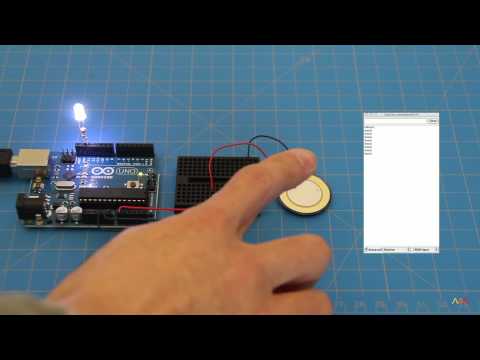
Arduino: Detect when two wires are connected

Arduino can detect if you cut the connection of a wire or you want implement a piezo sensor, basically the theory is the same.
One application, that I have tried at home, is to detect when the door is open and when is close.
You have to put 2 wires on the door that when it is closed, the two wires must make a bridge and break it when it is open.

The piezo works with the same concept , when you touch it, your finger does a bridge and then you can catch it with your Arduino.

This is a piezo sensor

CODE

void setup() {
pinMode(A0,INPUT);
}
void loop() {
   if (analogRead(A0) < 50) {
      //The two wires are doing a bridge
  } else {
     //The two wires are disconnected
  }
  delay(100);
}


You should try it and find out a good value but normally when the two wires are connected the value is zero.

This is an example of to connect the piezo on your Arduino


WIRING
Connect one wire on the ground pin and the other one in the A0 pin.


Monday, 18 June 2012

Android: Motorola Issue with Listview

Motorola Droid X and maybe other models, have an issue with ListView that you will not see the background when you don't have an item inside.

On this link you can follow the discussion and the solution, if you don't want to read all the thread and understand how to fix the problem, you can read below how fix it.

Solution:
On your ListView you need to add four parameters that makes your ListView transparent when you dont have any items

Layout

android:background="@color/transparent"
android:cacheColorHint="@color/transparent"
android:descendantFocusability="afterDescendants"           
android:overScrollFooter="@null"

Color reference
<color name="transparent">#00000000</color>